Aircraft Parts Module
This module contains a library of classes devoted to modeling aircraft parts.
The main purpose of this library is to model various types of aircraft parts. Currently only wing objects are suported, however in the future it is possible that fuselages as well as other parts will be added.
| SUMARRY OF THE CLASSES: | |
|---|---|
- Wing: Creates a wing aircraft. This wing is capable of modeling the
structures of the aircraft wing as well as the aerodynamics. The structures are modeled with a combination of beam models currently, however it is likely that Ritz method laminates will also incorporated for buckling prediction purposes. The aerodynamics are currently modeled with potential flow doublet panels.
Wing
-
class
AeroComBAT.AircraftParts.Wing(PID, p1, p2, croot, ctip, x0_spar, xf_spar, Y_rib, n_ply, m_ply, mat_lib, **kwargs)[source]¶ -
__init__(PID, p1, p2, croot, ctip, x0_spar, xf_spar, Y_rib, n_ply, m_ply, mat_lib, **kwargs)[source]¶ Creates a wing object.
This object represents a wing and contains both structural and aerodynamic models.
Args: PID (int): The integer ID linked to this part.
p1 (1x3 np.array[float]): The initial x,y,z coordinates of the wing.
p2 (1x3 np.array[float]: The final x,y,z coordinates of the wing.
croot (float): The root chord length.
ctip (float): The tip chord length.
- x0_spar (float): The non-dimensional starting location of the cross
section.
- xf_spar (float): The non-dimensional ending location of the cross
section.
- Y_rib (1xN Array[float]): The non-dimensional rib locations within
the wing. This dimension is primarily used to create wing-sections which primarily define the buckling span’s for laminate objects.
- n_ply (1xM Array[int]): An array of integers specifying the number
plies to be used in the model. Each integer refers to the number of plies to be used for at a given orientation.
- m_ply (1xM Array[int]): An array of integers specifying the
material ID to be used for the corresponding number of plies in n_ply at a given orientation.
- th_ply (1xM Array[int]): An array of floats specifying the
degree orientations of the plies used by the lamiantes in the model.
- mat_lib (obj): A material library containing all of the material
objets to be used in the model.
- name (str): The name of the airfoil section to be used for cross
section generation.
wing_SNID (int): The first node ID associated with the wing.
wing_SEID (int): The first beam element ID associated with the wing.
wing_SSBID (int): The first superbeam ID associated with the wing.
SXID (int): The starting cross-section ID used by the wing.
- noe (float): The number of beam elements to be used in the wing per
unit length.
- n_orients (int): The number of fiber orientations to be used in
each laminate.
- n_lams (int): The number of laminates required to mesh the desired
cross-section.
- meshSize (float): The maximum aspect ratio a 2D element may have in
the cross-section.
ref_ax (str): The reference axis to be loaded in the wing.
- chordVec (1x3 np.array[float]): This numpy array is used to orient
the cross-section in 3D space. It corresponds to the local unit x- vector in the cross-section, expressed in the global frame.
- typeXSect (str): The type of cross-section to be used by the wing
structure. Currently the suported typed are ‘boxbeam’, ‘laminate’, and ‘rectBoxBeam’. See the meshing class in the structures module for more details.
Returns: - None
-
addLiftingSurface(SID, x1, x2, x3, x4, nspan, nchord)[source]¶ Adds a potential flow lifting surface to the model.
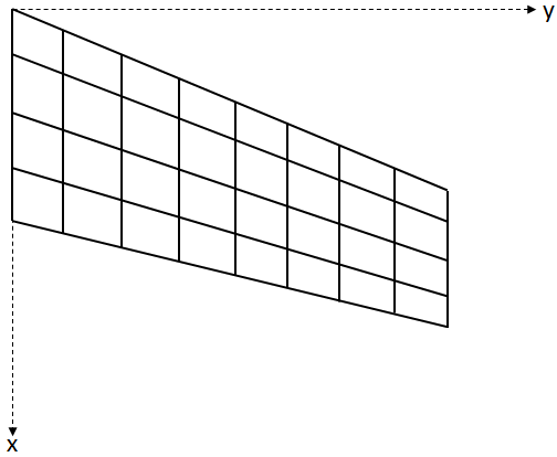
This method adds a potential flow panel aerodynamic model to the wing part. The x1,x2,x3, and x4 points correspond to the root leading edge, root trailing edge, tip trailing edge, and tip leading edge of the wing respectively. Currently the only suported types of panels are doublet- lattice panels to be used for unsteady aerodynamic models.
Args: - SID (int): The lifting surface integer identifier corresponding to
the lifting surface.
- x1 (1x3 numpy array): The point in 3D space corresponding to the
root leading edge point of the lifting surface.
- x2 (1x3 numpy array): The point in 3D space corresponding to the
root trailing edge point of the lifting surface.
- x3 (1x3 numpy array): The point in 3D space corresponding to the
tip trailing edge point of the lifting surface.
- x4 (1x3 numpy array): The point in 3D space corresponding to the
tip leading edge point of the lifting surface.
- nspan (int): The number of boxes to be used in the spanwise
direction.
- nchord (int): The number of boxes to be used in the chordwise
direction.
Returns: - None
Note
Mutliple surfaces could be added to the wing part.
Warning
In order to use the doublet lattice method, the chord lines of the lifting surface must run in the x-direction, and there can be no geometric angles of attack present. The geometry of a general wing can be seen in the figure below:
-
plotRigidWing(**kwargs)[source]¶ Plots the rigid wing.
This method plots the rigid model of the wing. This includes the reference axis of the beams, the cross-sections of the beams, and the lifting surfaces that make up the wing. This is an excellent check to perform before adding the part to a FEM model.
Args: - figName (str): The name of the MayaVi figure. ‘Rigid Wing’ by
default.
- numXSects (int): The number of cross-sections that each wing
section will display. By default it is 2.
- color (1x3 tuple(int)): This is a length 3 tuple to be used as the
color of the beam reference axes. Black by default.
Returns: - None
-